
3D Projection
Creating and projecting a 3D cube onto a shape layer using expressions in Adobe After Effects
Introduction
In this exercise we would like to create a 3D spinning cube and project it onto a 2D plane. All of that using a single shape layer and expressions.
This is a port of Daniel Shiffman’s Coding Challenge #112 (code for Processing).
Setup
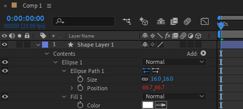
We want to draw the cube vertices with filled ellipses, and connect them with thin stroked lines. We would like to create a single point, apply an expression to its position, and then duplicate that point to create the other points. Once all points are created, we will draw the edges.
Math Utils
Manipulating 3D vectors (rotation, projection) is easier with matrices. Since there aren’t any built-in matrix utilities in the expression language, we must create our own. To avoid having a too long expression, we decide to put our matrix code in an external js file (e.g., “matrix.js”). This file can be imported into our our expression at runtime.
We only need basic stuff here: multiply a matrix and a vector, multiply two matrices… Here is our matrix library:
function vecToMatrix(v)
{
   var m = [];
   for (var i = 0; i < 3; i++)
   {
      m[i] = [];
   }
   m[0][0] = v[0];
   m[1][0] = v[1];
   m[2][0] = v[2];
   return m;
}

function matrixToVec(m)
{
   return [m[0][0], m[1][0], m.length > 2 ? m[2][0] : 0];
}

function matMatMul(a, b)
{
   var colsA = a[0].length;
   var rowsA = a.length;
   var colsB = b[0].length;
   var rowsB = b.length;
   var result = [];
   for (var j = 0; j < rowsA; j++)
   {
      result[j] = [];
      for (var i = 0; i < colsB; i++)
      {
         var sum = 0;
         for (var n = 0; n < colsA; n++)
         {
            sum += a[j][n] * b[n][i];
         }
         result[j][i] = sum;
      }
   }
   return result;
}

function matVecMul(a, v)
{
   var m = vecToMatrix(v);
   var r = matMatMul(a, m);
   return matrixToVec(r);
}
Creating The Vertices
First we need to import the matrix lib (“matrix.js”) into our ellipse position expression. This is done with the following line of code:
$.evalFile("F:/Documents/JSX/matrix.js");
Then we set some design variables and retrieve the index of the cube vertex:
r = 200; // cube size
distance = 2; // affects perspective
rotSpeed = 0.06; // in radians per frame

idx = parseInt(thisProperty.propertyGroup(3).name.split(" ")[1]) - 1;
We need to determine the location of each vertex from its index. To do that we can use the following formula (taken from math.stackexchange):
p = []; // 3D vertex position at start
bs = [];
for (i = 0; i < 3; i++)
{
	bs[i] = (idx >> i) & 1;
	p[i] = 0.5 * Math.pow(-1, bs[i]);
}
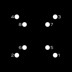
Note that the above formula will position the vertices in the following order (front face: 1-2-4-3, back face: 5-6-8-7):
Now that we have found the 3D starting position of the vertices, we can dive into the main part of this exercise. We basically loop through every previous frame, setup rotation matrices based on the current angle, apply 3 successive rotations (around Y, X, and Z axis), and finally project the 3D vertex to find its 2D position inside the shape layer. Here is the beast:
angle = 0;
for (t = 0; t <= time; t += thisComp.frameDuration)
{
	// rotation matrices (https://en.wikipedia.org/wiki/Rotation_matrix#Basic_rotations)
	rxMatrix = [[1,0,0], [0,Math.cos(angle),-Math.sin(angle)], [0,Math.sin(angle),Math.cos(angle)]];
	ryMatrix = [[Math.cos(angle),0,-Math.sin(angle)], [0,1,0], [Math.sin(angle),0,Math.cos(angle)]];
	rzMatrix = [[Math.cos(angle),-Math.sin(angle),0], [Math.sin(angle),Math.cos(angle),0], [0,0,1]];

	// do rotations (the order matters, here we chose it arbitrarily)
	p3d = matVecMul(ryMatrix, p);
	p3d = matVecMul(rxMatrix, p3d);
	p3d = matVecMul(rzMatrix, p3d);

	// increase rotation angle
	angle += rotSpeed;
}
// handle perspective
z = 1 / (distance - p3d[2]);

// project 3D point
projectionMatrix = [[z, 0, 0], [0, z, 0]];
p2d = matVecMul(projectionMatrix, p3d);

// scale result
mul(p2d, r);
To create the cube vertices we just need to duplicate the first Ellipse group 7 times.
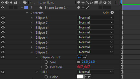
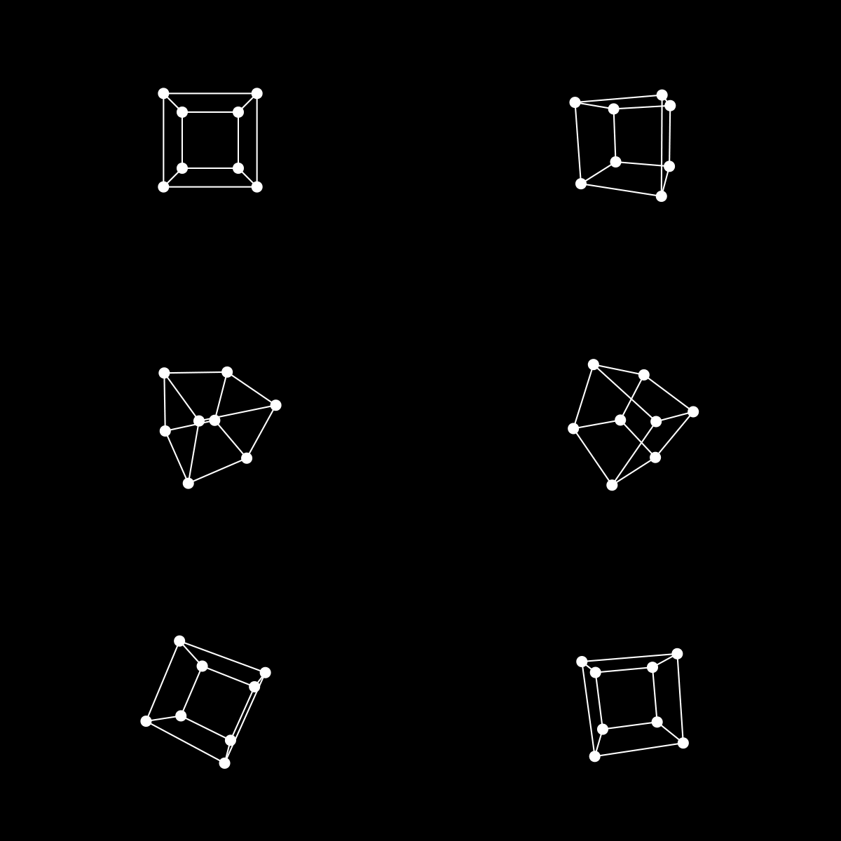
We obtain the following animation:
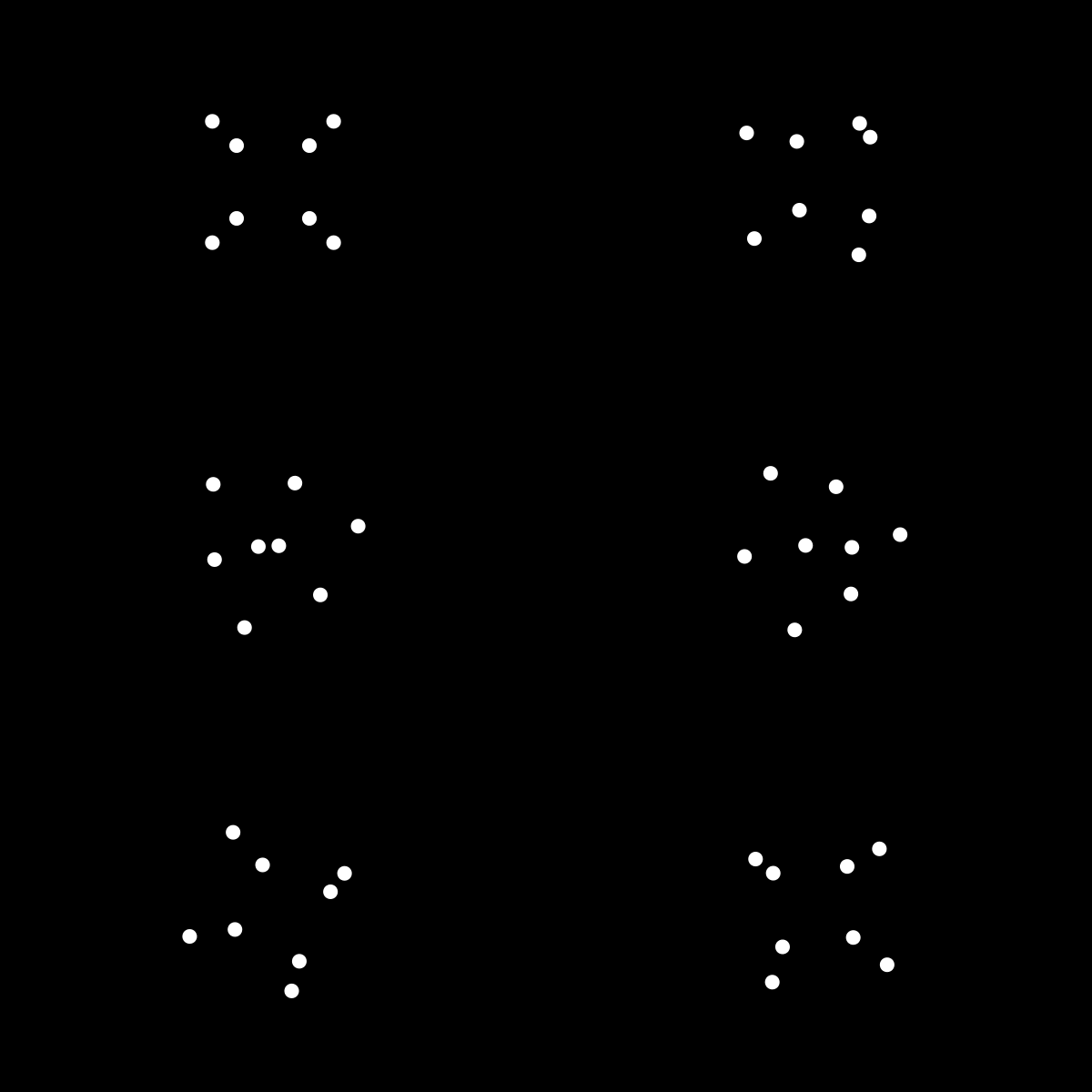
Great, our calculations seem correct. Now we need to connect those dots to finish the cube.
Creating The Edges
Since we cannot connect all vertices with a single path, we need to create multiple connecting lines. We want these lines to be constructed from the same unique expression, and control the connected vertices by specifying their indices in the shape’s group name.
Here is the first connecting path which connects the first four vertices (i.e., the front face):
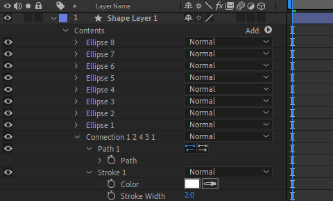
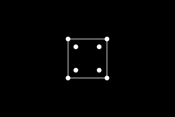
We apply the following expression to the path property of the connection:
indices = thisProperty.propertyGroup(3).name.split("Connection ")[1].split(" ");
pts = [];
for (i = 0; i < indices.length; i++)
{
	idx = indices[i];
	pt = content("Ellipse " + idx).content("Ellipse Path 1").position;
	pts.push(pt);
}
createPath(pts, [], [], false);
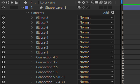
For creating every other connection we duplicate the first connection and rename it with the appropriate indices list for that connection. The final timeline looks like this:
It’s time to press the 0 key on the numpad to preview the final animation.
Conclusion
In this exercise we have shown how to project a 3D object onto a 2D plane using expressions. We have created our own matrix library to facilitate 3D calculations, and imported it into our expression. We used it to setup and manipulate rotation and projection matrices. Hope you find it useful!
You can also check ConnectLayers PRO, a tool that create lines that are dynamically linked to the layers using powerful path expressions. No keyframes at all!