All posts by Nab

Color Wheel

Manipulating shapes and colors using expressions

Download the After Effects project with the code!

Icon

color wheel article

Download

Introduction

As an exercise to practice our expression coding skills, we would like to create a color wheel using a single shape layer and expressions. The wheel should be made with colored arcs of varying hue, saturation and lightness. We want 4 levels of tint and 12 arcs per level (subdivisions). The following figure shows the different parts of the wheel and the notation we’ll use in the expressions:
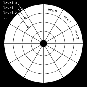
Structure of the wheel

Constructing The Base Arc

We want to create an initial arc, add expressions to it, and then duplicate that arc to construct the entire wheel. The setup consists of a shape group containing a trimmed stroked ellipse:
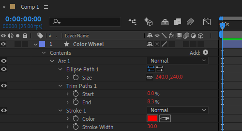
Setup for the base arc

Since the wheel is made of concentric circles, the size of each circle depends on the level. We apply the following expression to the ellipse size:

subdivs = 12;
idx = parseInt(thisProperty.propertyGroup(3).name.split(" ")[1]) - 1;
levelIdx = Math.floor(idx / subdivs);
strokeW = content("Arc " + (idx + 1)).content("Stroke 1").strokeWidth;
diam = 0.8 * thisComp.height - levelIdx * 2 * strokeW;
[diam,diam];

We add the following expression to the start property of the Trim Paths effector:

subdivs = 12;
idx = parseInt(thisProperty.propertyGroup(3).name.split(" ")[1]) - 1;
arcIdx = idx % subdivs;
arcIdx * (100 / subdivs);

The expression is the same for the end property, except the last line:

...
(arcIdx + 1) * (100 / subdivs);

The stroke width is set to 10% of the comp height:

0.1 * thisComp.height;

And finally we apply the following expression to the stroke color:

subdivs = 12;
numLevels = 4;
idx = parseInt(thisProperty.propertyGroup(3).name.split(" ")[1]) - 1;
levelIdx = Math.floor(idx / subdivs);
arcIdx = idx % subdivs;
h = arcIdx / subdivs; // hue
s = 1 - levelIdx / numLevels; // saturation (from high to low)
l = linear(levelIdx, 0, numLevels-1, 0.5, 0.3); // lightness (remap range)
a = 1; // alpha (doesn't affect the result here)
hslToRgb([h,s,l,a]);

This should produce something like this:
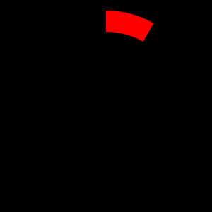
Structure of the wheel

Duplicating The Base Arc

Quite a lot of code for drawing a simple arc, but now comes the fun part. We simply press Ctrl+D (Cmd+D on Mac) to duplicate the base arc until the wheel is complete:
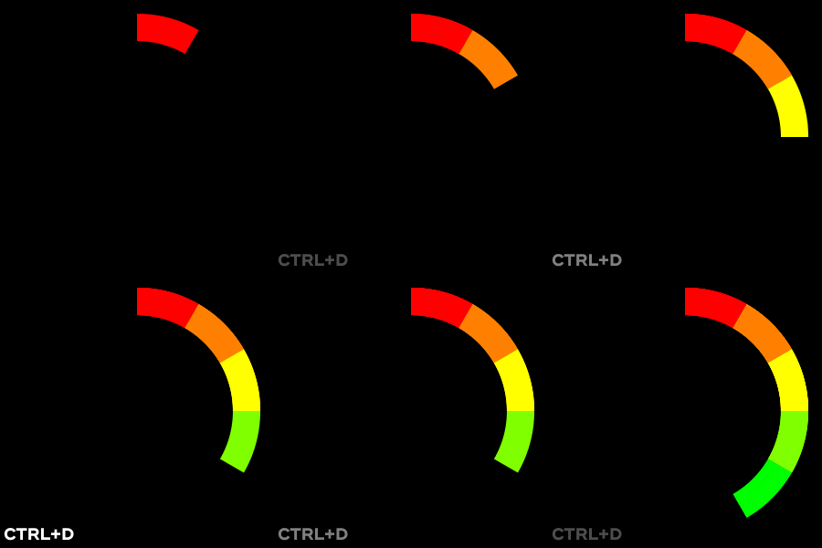
Duplicating the base arc

When the number of arcs reaches 48 (i.e., 4 x 12), the wheel is complete:ession to the ellipse size:
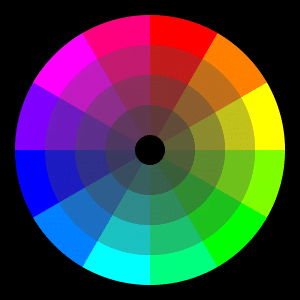
The complete wheel

Reveal Animation

As a bonus we would like to animate the construction of the wheel. To this end, we add a second Trim Paths effector to the base arc (don’t forget to remove every other arc):
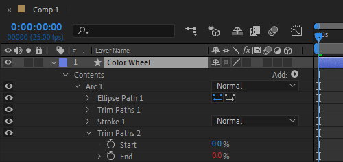
Adding a second trim to the base arc

We add the following trim end expression to sequentially reveal the arcs with a short delay:

arcRevealDur = 8; // duration in frames
delay = 2; // delay in frames
subdivs = 12;
numLevels = 4;
totalArcs = numLevels * subdivs;
idx = parseInt(thisProperty.propertyGroup(3).name.split(" ")[1]) - 1;
startT = idx * delay * thisComp.frameDuration;
endT = startT + arcRevealDur * thisComp.frameDuration;
linear(time, startT, endT, 0, 100);

The expression is the same for the out tangent except the vector points in the opposite direction:

Revealing the wheel

Conclusion

Through this little exercise we have seen how we can manipulate shapes and colors using simple expressions. Hope you find it useful!

You can also check ConnectLayers PRO, a tool that create lines that are dynamically linked to the layers using powerful path expressions. No keyframes at all!

Path Anatomy

Manipulating and visualizing path properties using expression

NOTE: AE CC 2017 or later is required

Download the After Effects project with the code!

Icon

Path Anathomy

Download

Initial Path

We first create a simple path animation using a shape layer. This will serve as a base path for our exercise. The position of the shape layer has been set to 0,0 in order to simplify our expressions.

Arbitrary initial path

The timeline looks like this:

Initial timeline

Recreating the path

We would like to recreate the initial path using a path expression applied to a new shape layer. This is done with the following expression:

myPath = thisComp.layer("Shape Layer 1").content("Shape 1").content("Path 1").path;
pts = myPath.points();
inTans = myPath.inTangents();
outTans = myPath.outTangents();
closed = myPath.isClosed();
createPath(pts, inTans, outTans, closed);

The initial path was using Fill only, so we use Stroke only for the replicated path. We also set the layer’s position to 0,0. The timeline looks like this:

Recreating the path using expression
The new path (black stroke) exactly matches the initial path (blue fill)

Traveling Along The Path

We would like to create a dot that travels along the path. We want the animation to span the entire comp duration: the dot should start its journey at t=0, and it should reach the end of the path at the end of the comp.

The dot is represented as a small filled and stroked ellipse:

Traveling along the path

We use the following ellipse position expression to make the dot traveling along the path:

myPath = content("Create Path").content("Path 1").path;
animDur = thisComp.duration;
travelProgress = time / animDur;
pt = myPath.pointOnPath(travelProgress);
Point on path

Visualizing Tangent Along The Path

We would like to visualize the tangent vector at the traveling point. To this end, we add two new shape groups for the in and out tangents:

Creating shapes for the in and out tangents

We add the following path expression to create the in tangent vector as a simple straight line of given length:

myPath = content("Create Path").content("Path 1").path;
animDur = thisComp.duration;
tgLen = 60; // length of in tangent in px
travelProgress = time / animDur;
pt = myPath.pointOnPath(travelProgress);
tg = myPath.tangentOnPath(travelProgress);
inTanPt = pt - tg * tgLen;
verts = [pt, inTanPt];
createPath(verts, [], [], false);

The expression is the same for the out tangent except the vector points in the opposite direction:

...
outTanPt = pt + tg * tgLen;
verts = [pt, outTanPt];
...
Visualizing the tangent along the path

Visualizing Normal Along The Path

To finish our exercise we would like to visualize the normal vector at the traveling point. We first add a new shape group:

Creating shape for the normal

Then we apply the following path expression:

myPath = content("Create Path").content("Path 1").path;
animDur = thisComp.duration;
nrmLen = 35; // length of normal in px
travelProgress = time / animDur;
pt = myPath.pointOnPath(travelProgress);
nrm = myPath.normalOnPath(travelProgress);
nrmPt = pt + nrm * nrmLen;
verts = [pt, nrmPt];
createPath(verts, [], [], false);
Visualizing the normal along the path

Conclusion

Through this little exercise we have seen all path properties available in expression. We were able to create a path by specifying its vertices and tangents, and were able to visualize tangent and normal vectors of a point traveling along the path. Hope you find it useful!

You can also check ConnectLayers PRO, a tool that create lines that are dynamically linked to the layers using powerful path expressions. No keyframes at all!

Trim Path Tricks

Attaching a layer to the end of a path using expression

NOTE: AE CC 2017 or later is required

Download the After Effects project with the code!

Icon

trim path trick

Download

Start Simple

We first create a simple horizontal path using a shape layer. We make sure to set the layer’s position to 0,0 so the coordinates of the vertices will correspond to points in comp space (this will simplify a little bit our expression).

Start with a simple horizontal line

Then we add a Trim effector and create two keyframes to animate the end of the path from 0% to 100%. For the second key, we apply an Easy Ease In and multiply the influence of the incoming velocity by two (i.e., from 33.33% to 66.66%).

Now we create the layer we would like to attach to the end of the path. We make sure its position corresponds to the center of the comp (the default value) and its anchor point is located at the left hand side of the layer.

The layer to be attached to the path

The timeline looks like this:

Simple setup

To attach the layer to the path, we need to find the location (in comp space) of the end point of the path. This is done with the following position expression:

shapeGroup = thisComp.layer("Path Layer").content("Shape 1");
myPath = shapeGroup.content("Path 1").path;
trimEnd = shapeGroup.content("Trim Paths 1").end / 100;
endPt = myPath.pointOnPath(trimEnd);
The origin of the layer is “pushed” by the end of the path

Add Salt

Let’s see if we can add a small gap between the end of the path and the attached layer. Since our path is a straight horizontal line, we only need to shift the layer to the right along the x-axis. We add the following code to the previous expression:

...
gap = 15; // distance in px between the path and the layer
endPt + [gap,0];
Adding space bewteen the end of the path and the layer

Add Pepper

Now we would like to try with a more complex path, say an arbitrary Bezier path. Note that the end vertex has a non-zero tangent vector.

A more complex path

The code for the gap must be changed to take into account the direction pointed by the path (i.e., the tangent vector at the end of the path):

...
gap = 15; // distance in px between the path and the layer
tg = myPath.tangentOnPath(trimEnd);
endPt + gap * tg;
Adjusting the gap code

Add Cayenne Pepper

Now we would like to rotate the layer so it’s oriented along the path. To this end, we could use the corresponding built-in feature in AE:

Built-in auto-orientation along the path

Not that bad, but notice how the layer suddenly changes its orientation at the end of the animation. So let’s try to orient the layer using the following rotation expression (don’t forget to turn Auto-orient off before applying the expression):

shapeGroup = thisComp.layer("Path Layer").content("Shape 1");
myPath = shapeGroup.content("Path 1").path;
trimEnd = shapeGroup.content("Trim Paths 1").end / 100;
tg = myPath.tangentOnPath(trimEnd);
a = Math.atan2(tg[1],tg[0]);
radiansToDegrees(a);
Custom auto-orientation along the path

Great, the orientation looks correct now.

Cake For Dessert

For better control we could precompose our layer and make some design changes in the precomp. We don’t want the (precomp) layer to overlap the end of the path so we position the content of the precomp at the center of the precomp, and left-align the content since our path animation goes from left to right.

Working with a precomp
Using a precomp provides more control

Conclusion

We have shown how to attach a layer to the end of a path using simple expressions. Hope you find it useful!

If not, you can use or tool Connect Layers Pro to add arrow heads to your path!

DelaunayTracking

DelaunayTracking

Inspired by the work of Memo Akten for the Wombats music video, we developed a little real-time app that takes a video as input, finds a set of interesting feature points, constructs a delaunay triangulation with it, and tracks the features through the footage. Blobs of similar pixels are also detected, triangulated and tracked. Controllers allow to composite the created vector elements (triangles, edges, points) with the original footage.